


In settings like factories, offices, or residences where electricity is utilized, having a robust grounding system is crucial. Grounding guarantees that in the event of electrical mishaps, such as short circuits, the electricity can be safely diverted. This safeguards individuals and devices from potential hazards. To assess the effectiveness of the grounding, professionals conduct earth resistance tests, commonly known as earth pit testing. These tests generate detailed reports indicating the efficiency of the grounding system or identifying issues that require attention. This article will elaborate on the significance of these tests and outline their procedures.
What is Earth Resistance?
Earth resistance is the measure of how effectively the ground can conduct electricity, gauging its opposition to electric current flow. Measured in ohms using instruments like earth testers, it’s crucial in electrical systems for the safe dissipation of fault currents and for preventing electric charge buildup. Low earth resistance is favorable, indicating efficient current conduction for enhanced safety. Conversely, high earth resistance may compromise safety. Regular ground resistance testing and earth resistance testing assess the effectiveness of the grounding system, which is crucial in industrial, commercial, and residential settings.
Earth pit resistance specifically refers to the resistance of the ground around the earth pit, where the grounding electrode is placed. Maintaining low earth pit resistance ensures that the grounding system can efficiently handle fault currents, thereby enhancing overall electrical safety.
How To Measure Earth Resistance Testing?
The process of establishing proper earthing begins with the placement of earth electrodes near the structure requiring grounding. These electrodes, made from materials such as copper, steel, or galvanized iron, are strategically buried at various locations. The selection of electrode material is based on the electrical system’s requirements and the soil resistivity of the area.
Key factors impacting earth pit resistance, such as soil composition, temperature, moisture levels, and electrode depth, play a significant role in the earthing system. The primary objective of earthing is to safely channel leakage current, and this system is integrated with an automatic cutoff device to ensure power supply safety.
Regular ground resistance testing and earth resistance testing are essential to assess the effectiveness of the earthing system in maintaining a safe electrical environment. These tests involve measuring the resistance of the ground and the earth pit to ensure that they can efficiently handle fault currents. Effective earth pit testing ensures that the grounding system remains reliable, safeguarding both individuals and equipment from electrical hazards.
Importance of Earth Resistance Testing
A grounding system’s primary function is to provide a low-resistance path for fault currents to dissipate into the earth, thereby preventing electrical shock and fires. Their inspection frequency usually depends upon the risk assessment, but here is a general formula that can be helpful in routine inspections.
Over time, soil conditions, corrosion, and system modifications can compromise the grounding system’s integrity. Earth resistance testing, ground resistance testing, and earth pit testing are essential to evaluate the system’s effectiveness. These tests use an earth resistance meter to ensure the system maintains a low-resistance path for fault currents. Resistance earthing creates an intentional low-resistance path, critical for electrical safety. Regular earth pit testing identifies issues with soil, corrosion, or modifications affecting performance. Consistent testing ensures the grounding system can efficiently dissipate fault currents, preventing electrical shocks and fires.
Inspection Frequency = Risk Assessment Score / Maximum Possible Score x 100
Over time, soil conditions, corrosion, and system modifications can compromise the integrity of the grounding system. Earth resistance meter is used to measure this, as shown in Figure 1. This underscores the importance of regular Earth Resistance Tests to:
- Ensure the safety of personnel working with electrical equipment.
- Maintain the effectiveness of lightning protection systems.
- Prevent equipment damage and operational disruptions.
- Comply with electrical safety standards and codes.

Conducting an Earth Resistance Test
An Earth Resistance Test typically involves injecting a known current into the grounding system and measuring the voltage drop. The resistance is then calculated using Ohm’s law:
R = V/I
Where:
R = Earth Resistance (ohms)
V = Voltage Drop (volts)
I = Injected Current (amperes)
The test is performed at multiple locations within the grounding system to ensure uniformity and identify any problem areas.
Earth Resistance Test Report: Data and Report
A comprehensive earth pit test report is critical for evaluating the grounding system’s condition and safety. Similarly, an earth resistivity test report provides essential insights into the soil’s ability to conduct electricity, which is vital for maintaining an effective grounding system. These reports collectively ensure that the grounding infrastructure remains reliable and safe.
Here’s how the technical data is presented in such a report:
1. Test Date and Location
The report begins with essential information on where the test was conducted. In this case, near the Main Substation of the Transformer.
2. Test Equipment Details
Details about the test equipment used, including the make and model of the earth tester, current injection device, and measurement probes, are included. This ensures transparency and traceability of the testing process.
3. Test Procedure
The report outlines the test procedure, describing how the Earth Resistance Test was conducted step by step. This section may include:
- Pre-test preparations.
- The number of test points or measurement locations.
- The sequence of measurements.
- Safety precautions were taken during the test.
4. Measurement Data
The heart of the Earth Resistance Test Report is the measurement data.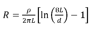
Where,
Ρ = Soil resistivity in Ώ-m
L = length of electrode buried in soil (m)
d = Diameter of Earth rod (m)
This data includes:
- Measurement Point
A reference to the measurement’s location (e.g., Grounding electrode near Main Panel).
- Injected Current (I)
The known current injected into the grounding system is typically measured in amperes.
- Voltage Drop (V)
The voltage drop across the grounding system during the test, measured in volts.
- Earth Resistance (R)
Calculated using Ohm’s law (R = V / I), expressed in ohms.
Electrical Check
The data is presented in tabular format, making it easy to review and analyze the results. Since the resistance value is less than 1 Ω, these are acceptable. Here’s a table for two measurement points:
| Measurement Point | Injected Current (A) | Voltage Drop (V) | Earth Resistance (Ω) |
| Electrode near Main Panel | 25 | 5.2 | 0.208 |
| Grounding Rod at Substation | 50 | 7.6 | 0.152 |
Mechanical Checks and Visual Inspection
| Item | Description |
| 1 | Inspect for physical damage/defects. |
| 2 | Check the tightness of all connections. |
| 3. | Check for cleanliness and external contamination |
Conclusion
The earth pit test report plays a crucial role in guaranteeing the safety and reliability of electrical systems. This report thoroughly evaluates the condition of the grounding system by analyzing technical data, including current injection, voltage drop, and the calculated earth resistance. Consistent earth resistance testing and ground resistance testing, along with maintaining detailed records, are extremely important to ensure compliance with safety regulations. This proactive approach ensures the optimal performance of electrical systems, mitigating the risk of accidents and prioritizing the safety of people and assets.
The earth testing procedure involves injecting a known current into the grounding system and measuring the voltage drop to calculate earth resistance. An earth resistivity test report further assesses the soil’s ability to conduct electricity, which is vital for an effective grounding system. Together, these tests provide a comprehensive overview of the grounding system’s performance, ensuring ongoing safety and reliability.


