


For the purpose of designing, building, and running solar power plants, a single-line diagram (SLD) is a crucial tool. It offers a simplified visual representation of the electrical system, enabling engineers, technicians, and users to quickly understand the parts, connections, and operation of the system. In this article, we will look at how a solar plant’s SLD works and give an example of SLD to show how its parts are assembled together.
What is Single Line Diagram (SLD)
A Single Line Diagram (SLD), commonly referred to as a Schematic Diagram, is also known as one line diagram. Single Line Diagram is a condensed illustration of the parts of an electrical system that shows how they are organized. It can also provide important facts about the installation, such as the voltage and current of the system’s stringing3. The SLD is an illustration of the electrical infrastructure of the solar power plant, presented as a single line with symbols and names. The main system elements are shown, along with how they are connected and how the electrical energy moves through the system.
What Does a Single-Line Diagram Look Like?
Single-line diagrams use simple symbols to represent different parts of power systems. The power source is shown at the top of the diagram, making it easy to follow the path of power from one part to another. This also helps in seeing if there are backup power paths running alongside the main one.
What is a Single-Line Diagram Used For?
A single-line diagram shows how power is spread out in a building. It’s like a map that needs to be correct and updated when things like machines are added, taken away, or changed.
Here’s why using a single-line diagram in your data center is helpful:
- Knowing Your Power System:
- Helps you understand how power is set up in your place.
- Keeping Things Reliable:
- Make a record of backup power paths so your system stays reliable.
- Making Things Easier:
- Makes planning, fixing problems, and doing maintenance easier and more efficient.
- Following Rules:
- Ensures you follow safety rules and codes like NFPA-70E.
- Keeping People Safe:
- Helps keep the place safe for everyone working there.
AC side Single Line Diagram (SLD)
The simplified representation of the electrical connections and parts on the AC side of a solar module or panel is known as an AC side Single Line Diagram (SLD) for a Solar Module. In order to produce direct current (DC) power from sunlight, several solar cells are linked in series and parallel to form a single unit known as a solar module. A simple illustration of an AC side SLD for a solar module is shown below:
Symbols frequently represent the solar panels or photovoltaic (PV) modules
Solar Panels (PV Modules)
Symbols frequently represent the solar panels or photovoltaic (PV) modules at the very beginning of the SLD. Sunlight is converted into direct current (DC) electricity through these panels, which serve as the primary energy source.
ICOG panel
Crompton 11kV ICOG VCB Panel is an electrical panel that contains Vacuum Circuit Breakers (VCBs) designed to operate at a voltage level of 11 kilovolts (11kV).
MCR
The Main Control Room (MCR), in the context of a solar module, often refers to a centralized facility where the monitoring, control, and administration of the complete solar installation take place. For controlling the performance and management of the solar PV system, the MCR acts as the control hub.
ICR
The inverters, which transform the DC (direct current) power produced by solar modules into AC (alternating current), are kept and administered in an area designated as an Inverter Control Room (ICR) inside a solar PV (photovoltaic) plant. The ICR is a critical component of larger solar installations, especially utility-scale solar farms.
Central Inverter
The central inverter for a solar module with a capacity of 2500 kVA (kilovolt-ampere) is a large-scale inverter that can manage a lot of electrical output. The apparent power capability of the inverter is 2500 kVA. The total power, which includes both actual (active) power and reactive power, is measured by this. It generally relates to the highest AC power output the inverter can manage in solar applications.
Switchgear and Circuit Breakers
Switches and circuit breakers are represented by several symbols found throughout the SLD. In addition to isolating problematic system components and guarding against overloads and short circuits, these devices assist in controlling the flow of power.
Distribution Panels
Distribution panels are employed to divide the AC power into several circuits for usage inside the building or export to the grid. They are shown as symbols with labels that describe where they are and what they do.
Monitoring and Control
Symbols for monitoring and control devices can be seen throughout the entire SLD. With the help of these gadgets, system performance can be remotely monitored, allowing operators to make any necessary modifications.
DC side Single Line Diagram (SLD)
A simplified graphical representation of the direct current (DC) electrical components and their connections in a solar power system is called a DC side Single Line Diagram (SLD) for a solar installation. It displays the path taken by electricity as it moves from solar panels to other direct current (DC) parts before being changed to alternating current (AC) for usage in buildings or connection to the grid.
Solar array
An array is a component of your solar system that is made up of numerous solar panels. Your family’s energy requirements and the location of your roof will determine the size of your solar array 7. Solar cells, also known as photovoltaic cells, are the building blocks of solar panels, which are assembled to form solar arrays. An array is a collection of solar panels. This phrase can be used by your solar advisor when describing your energy requirements and the number of solar panels (or the size of your array) required to power your house.
Combiner Boxes
Combiner boxes are the next in step, and they connect together one or more strings of DC output from several solar panels. Usually, each string consists of a number of panels linked in parallel.
Inverter
The inverter transforms the DC electricity produced by the solar cells into AC electricity. This is essential due to the electrical grid and the majority of appliances rely on AC.
Grid Connection Point
The point at which the solar system is connected to the main power grid is known as grid connection point. The grid can be recharged with extra electricity.
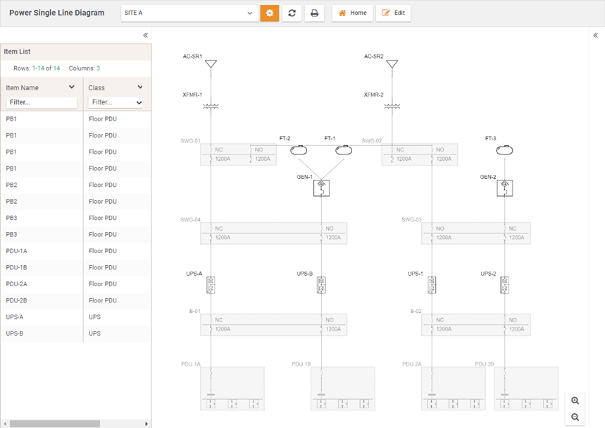
Example SLD of a Solar Power Plant
Here is a simple SLD illustration of a solar power plant:
For an ideal solar panel SLD:
– At the beginning, there is a representation of the solar panels (PV modules).
– DC output from several panels is combined into strings by combiner boxes.
– Inverters convert DC to AC electricity.
– Transformers increase the voltage to connect to the grid.
– Switchgear and circuit breakers control power flow.
– To divide the AC electricity for local usage or grid export, distribution panels are used.
– The grid connection point interfaces with the electrical grid.
For a better understanding of a solar power plant’s electrical system, a single-line diagram (SLD) is a crucial tool. With the use of symbols and labels, it condenses complicated systems into a single, simple-to-read line. SLDs provide efficient design, troubleshooting, and upkeep of solar projects for engineers and operators. For solar power plants to operate effectively and safely, it is important to understand the SLD’s components and their roles.


